

 English
  русский
  عربى
عربى 
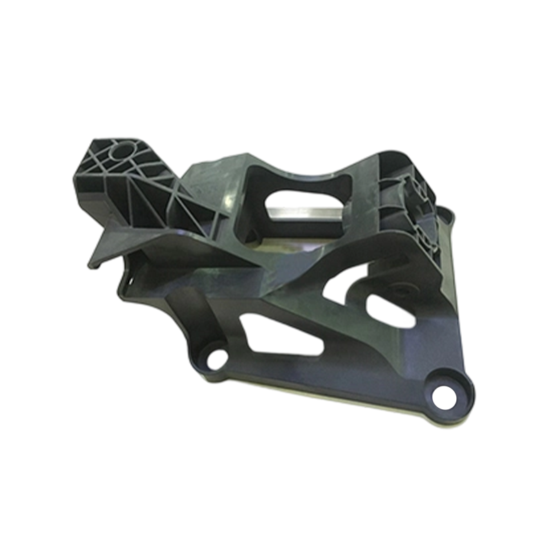
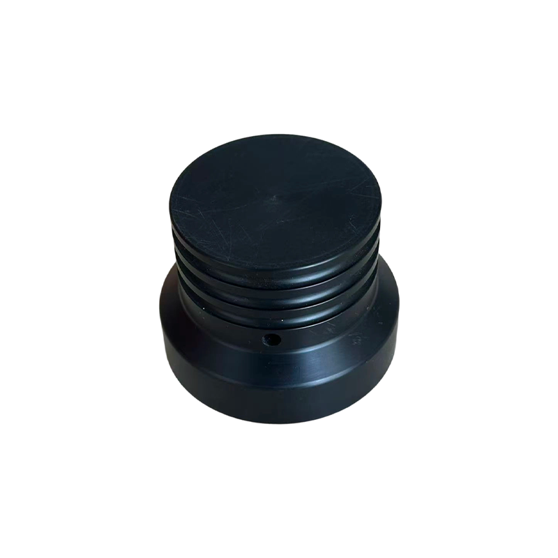
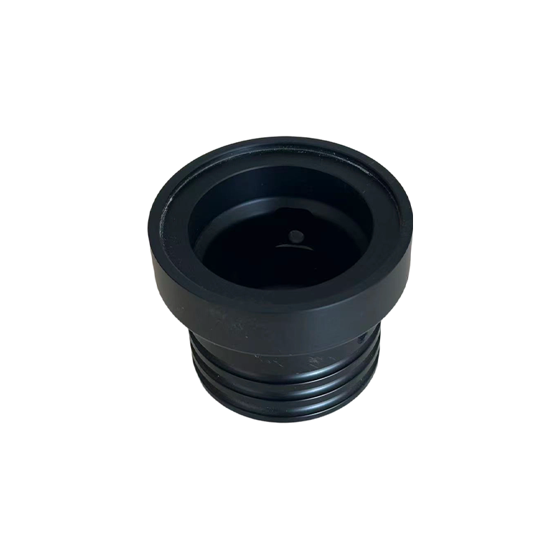
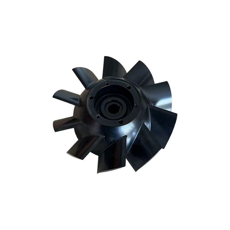
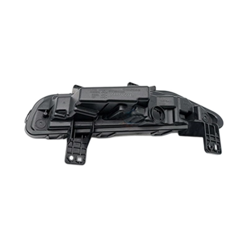
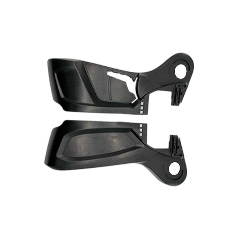
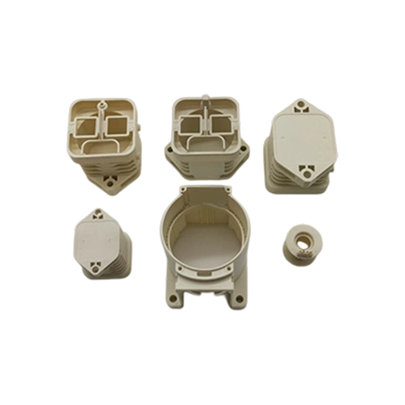
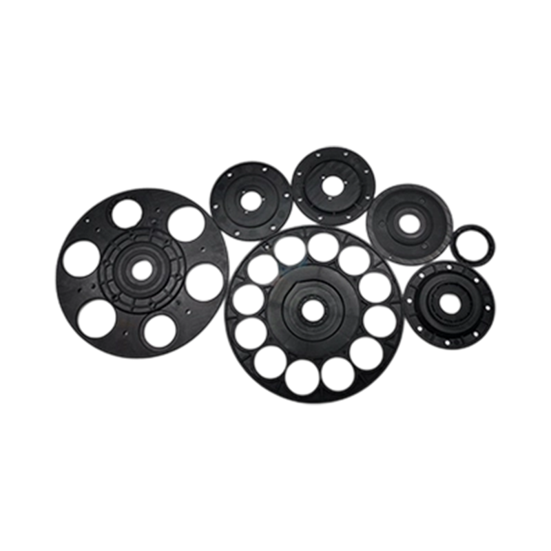






Resin Behavior and Material Selection for Precision Molded Components
Suzhou Kokosili approaches every molding program by first interrogating how a resin will actually behave under shear and thermal load, not just what its datasheet promises. Semi-crystalline materials like PA66 and POM shrink anisotropically as they cool, which means wall sections that look identical on a drawing can pull to different final dimensions depending on flow direction. Amorphous resins such as ABS and polycarbonate shrink more predictably but are far less forgiving of residual stress, showing stress-whitening or cracking around gates and ejector pins if cooling isn't managed correctly.
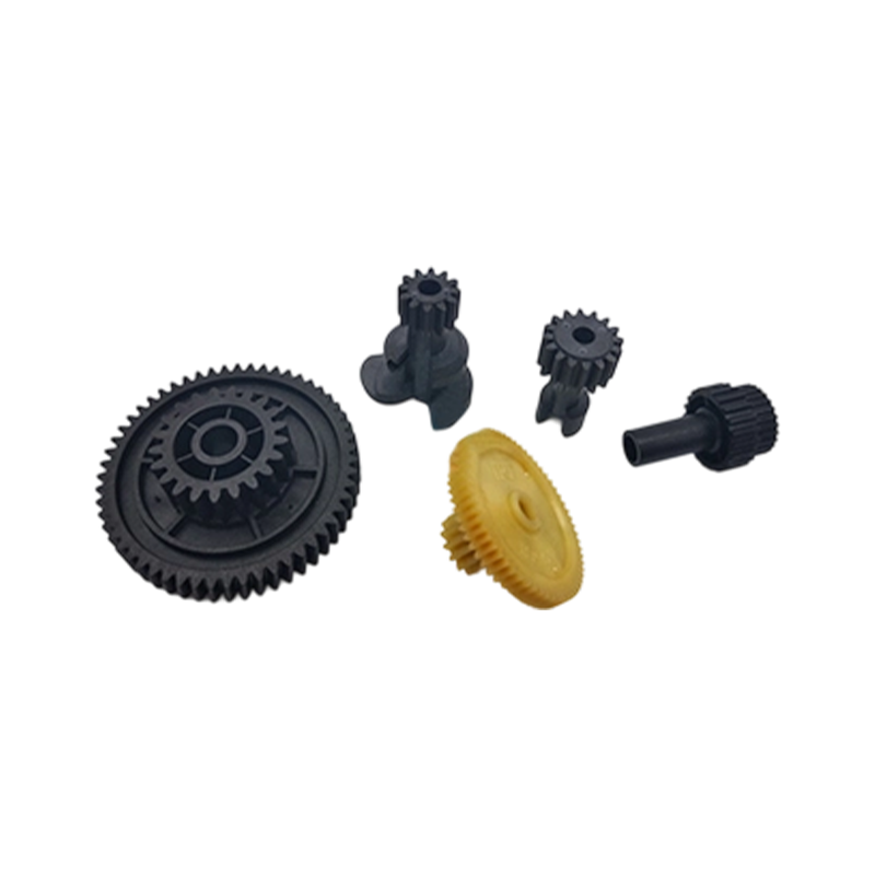
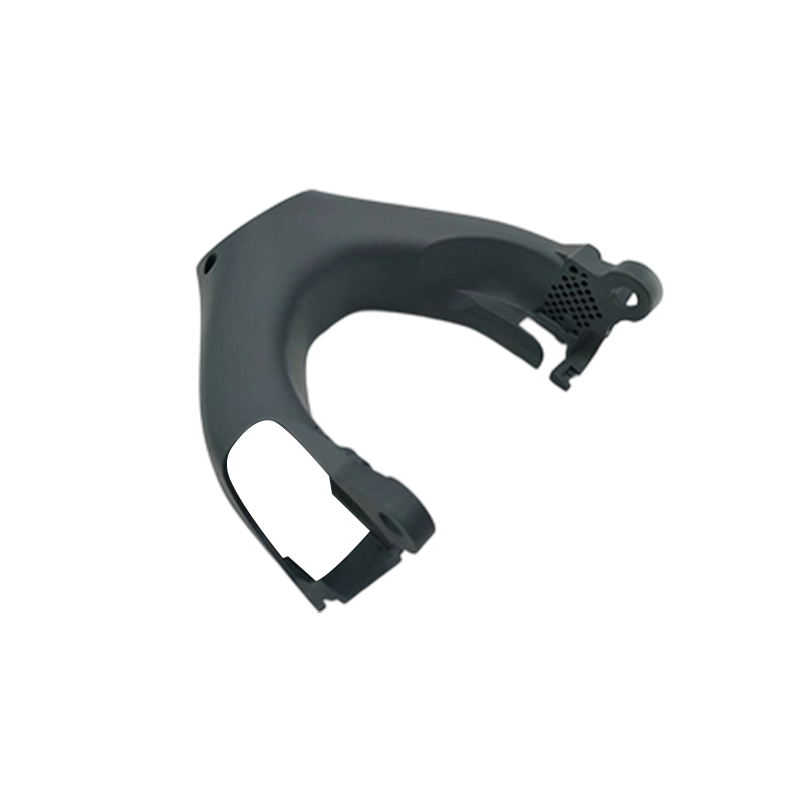
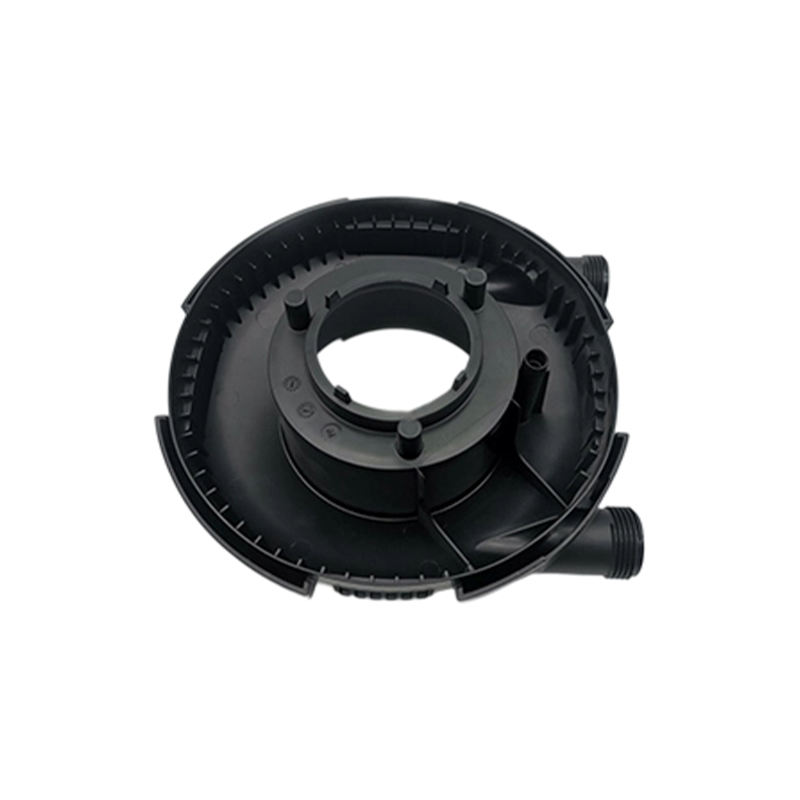
Melt flow index (MFI) is often treated as a single number, but for high-precision parts it should be read alongside mold temperature and injection speed together, since a resin with high MFI can still hesitate and short-shot in a thin-wall section if the mold runs cold. For components destined for structural or load-bearing roles, glass-filled or mineral-filled grades introduce their own complication: fiber orientation near the gate creates localized stiffness differences that pure isotropic material models don't predict, which is why prototype tooling trials matter more than simulation alone for tight-tolerance Plastic Injection Molding Part production.
Mold and Gate Design Decisions That Determine Dimensional Accuracy
Gate placement decides more about a finished part's dimensional stability than most buyers realize. A gate positioned at the thickest section allows the mold to pack out sink-prone areas before the gate freezes, but a gate at a thin section starves downstream material and locks in voids that only show up later as warping or premature fatigue failure. Our engineering team runs mold-flow analysis before cutting steel, in the process design and mold development phase that this facility manages internally, so that gate location, weld line position, and venting are resolved before a single cavity is machined.
- Balance runner lengths in multi-cavity tools so each cavity fills at the same rate and pressure.
- Place vents at the last-to-fill regions, typically 0.02–0.04mm deep, to avoid trapped air and burn marks.
- Size ejector pins and their placement to distribute demolding force evenly across ribs and bosses.
- Set cooling channel spacing uniformly around the cavity to prevent differential shrinkage between regions.
Wall thickness transitions deserve particular attention: an abrupt step from a 3mm boss into a 1mm wall creates a pressure drop that the packing phase can't fully compensate for, so designers should target gradual transitions with at least a 3:1 ratio wherever geometry allows.
Diagnosing and Preventing Common Defects Before They Reach Final Inspection
Sink marks, flash, and warpage share a common root cause more often than not: uneven packing pressure across the cavity. Rather than treating each defect as a separate problem to solve with a separate fix, experienced process engineers look at the packing profile as a whole. A sink mark opposite a rib usually means the rib is starving the surrounding wall of material during the hold phase, and the fix is frequently a longer hold time or slightly higher pack pressure rather than a design change.
| Defect | Common Root Cause | Primary Adjustment |
|---|---|---|
| Sink marks | Insufficient packing near thick sections | Extend hold time / raise pack pressure |
| Flash | Excess clamp deflection or worn parting surfaces | Verify clamp tonnage / re-machine parting line |
| Warpage | Asymmetric cooling across the cavity | Rebalance cooling channel layout |
What separates a component that passes first-article inspection from one that requires rework is usually process discipline during the trial phase, tracking cavity pressure curves shot to shot to catch drift before it produces an out-of-tolerance part, a practice our team relies on when qualifying new tooling here at Kokosili.
Matching Molding Capability to Application-Specific Standards
Battery and thermal management housings demand flatness and flame-retardant grades that hold dimension under repeated thermal cycling.
Traceable resin lot control and cleanroom-adjacent handling protect against contamination and ensure repeatable biocompatible performance.
High-cycle wear components need consistent friction and impact properties across long production runs without dimensional drift.
Lightweight structural brackets require certified material traceability and tight geometric tolerance verification on every batch.
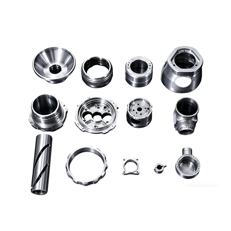
Every industry sets its own bar for what "acceptable" means on a molded part, and that's exactly why a molder's internal capability, machining, casting, and assembly under one roof, matters as much as the molding process itself. This is the operating model applied across the full production floor, allowing tooling revisions, secondary machining, and assembly to happen without handing a part off between vendors and re-introducing tolerance stack-up at every transfer. Buyers evaluating a supplier for a Plastic Injection Molding Part program should ask not just what tolerance a molder can hit on a good day, but what process controls keep that tolerance stable across a full production run.
