

 English
  русский
  عربى
عربى 


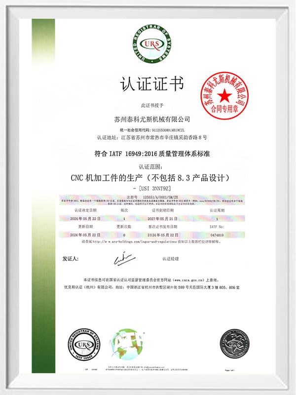
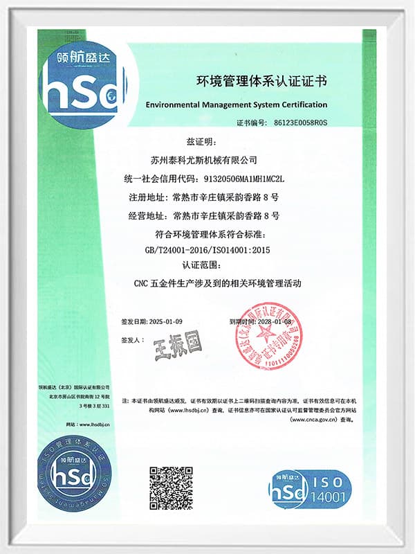
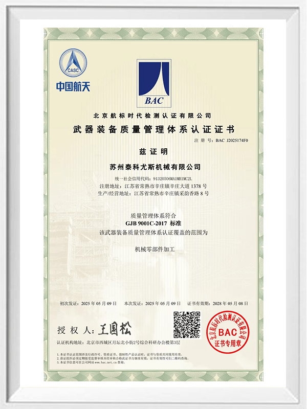


High Precision Components Quality Control: Configuring CMM, Laser Interferometer, and Profilometer Based on Tolerance Classes and Inspection Frequency
For the production of High Precision Components, a well-designed quality control (QC) system is as critical as the machining process itself. Selecting the right measuring instruments—Coordinate Measuring Machines (CMM), laser interferometers, profilometers, and others—depends on two primary factors: the tolerance class of the features being measured, and the required inspection frequency (sampling rate). Over-investing in ultra-precise instruments for coarse-tolerance parts wastes capital, while under-instrumenting tight-tolerance features risks shipping out-of-spec parts. This article provides a structured methodology for instrument configuration based on industry standards and practical production needs.
Understanding the Role of Each Instrument in High Precision Components QC
Each measurement instrument serves a distinct purpose and operates at a different level of precision:
- Coordinate Measuring Machine (CMM): The workhorse of dimensional inspection. CMMs measure 3D geometric features—lengths, angles, positions, form errors (flatness, roundness, cylindricity), and profiles. They are available in bridge, gantry, and horizontal-arm configurations, with accuracy ranging from ±0.5µm to ±5µm depending on the model.
- Laser Interferometer: The gold standard for linear displacement and machine calibration. It measures with sub-micron accuracy (typically ±0.1µm over 1m) and is used for verifying CNC machine positioning accuracy, ball screw pitch errors, and thermal drift compensation.
- Profilometer (contact or optical): Measures surface texture—roughness (Ra, Rz), waviness, and primary profile. Contact stylus types achieve 0.01µm resolution, while optical (white light or confocal) profilometers are faster and non-contact, ideal for soft or reflective surfaces.
- Laser Tracker / Total Station: Used for large-scale alignment and assembly verification, particularly in aerospace or energy storage modules where components span several meters.
Matching Instruments to Tolerance Classes
For High Precision Components, tolerance classes are typically defined by the ISO 286 system (IT grades) or by geometric tolerancing (GD&T). The following table provides a reference matrix for instrument selection based on feature tolerance:
| Tolerance Class / Typical Feature | Typical Tolerance Range | Primary Instrument | Supplementary Instrument | Measurement Uncertainty Requirement |
|---|---|---|---|---|
| IT5–IT6 (precision shafts, bearings) | ±0.002 – ±0.005mm | High-accuracy bridge CMM (±0.5µm) | Laser interferometer (machine verification) | ≤ 10% of tolerance (e.g., 0.0005mm) |
| IT7–IT8 (general mechanical fits) | ±0.010 – ±0.025mm | Shop-floor CMM (±1.5µm) | Digital height gauge, bore gauge | ≤ 20% of tolerance |
| IT9–IT10 (sheet metal, castings) | ±0.05 – ±0.15mm | Portable CMM (articulated arm) | Laser tracker (large parts) | ≤ 25% of tolerance |
| Surface roughness (functional surfaces) | Ra 0.2 – 1.6µm | Contact profilometer | Optical profilometer (high speed) | ±5% of Ra value |
| Large assemblies / alignments | ±0.1 – ±0.5mm over 5m | Laser tracker | Total station, laser level | ≤ 0.05mm |
Determining Inspection Frequency (Sampling Strategy)
Inspection frequency is determined by production volume, process stability (Cpk), and part criticality. A rational sampling plan balances quality risk against inspection cost. The following principles apply:
- 100% inspection: Required for safety-critical High Precision Components (aerospace flight controls, medical implants) or when process Cpk < 1.33. Automated CMM cells or in-line probing systems are used for efficiency.
- High-frequency sampling (every 5–20 parts): For features with IT6–IT7 tolerances and moderate process capability (Cpk 1.33–1.67). Shop-floor CMMs or dedicated gauges are used with SPC charting.
- Low-frequency sampling (every 50–200 parts): For stable processes (Cpk > 1.67) or less critical features. Portable CMMs or manual gauges are sufficient.
- First-article and periodic verification: Full dimensional and surface characterization using CMM + profilometer at the start of each shift or after any process change. Laser interferometer verification is performed monthly or quarterly for machine calibration.
Practical Configuration Strategy for High Precision Components Production
Based on the above principles, a well-equipped production facility should maintain a tiered instrument pool:
- Tier 1 – Metrology lab instruments (reference level): High-accuracy CMM (±0.5µm), laboratory profilometer, and laser interferometer. Used for periodic verification, process validation, and dispute resolution. These are kept in a temperature-controlled environment (20±0.5°C).
- Tier 2 – Shop-floor instruments (production level): Rugged CMMs (±2µm), CNC tool setters, and digital indicators. Used for daily inspection routines, first-article inspections, and SPC sampling. These instruments are calibrated daily using certified reference artifacts.
- Tier 3 – In-process probing systems: Touch probes and tool setters integrated into CNC machines. Used for setting tool offsets, measuring critical features in-cycle, and performing automatic tool wear compensation. They reduce manual inspection time and enable real-time process adjustment.
Our Quality Instrumentation Infrastructure
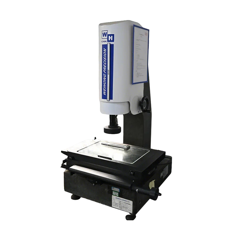
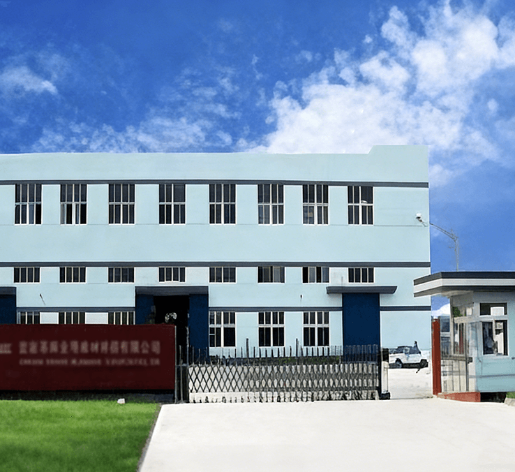
At our group, the quality of High Precision Components is ensured through a comprehensive instrumentation strategy. Techuse Machinery operates a dedicated metrology room equipped with a Zeiss high-accuracy CMM (accuracy ±0.6µm) and a Taylor Hobson contact profilometer for surface roughness verification. In addition, our CNC machines are fitted with Renishaw in-process probing systems, allowing for closed-loop dimension control during production.
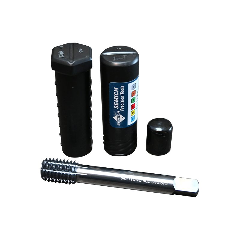
Our tooling division, SEMICH Precision Technology, provides not only cutting tools but also guidance on measurement best practices, including instrument selection for specific material groups and geometries. Cocosili ensures that quality plans and measurement reports are translated and delivered to global clients in a clear, standardized format.
Frequently Asked Questions (FAQ)
- Q1: How does Suzhou Kokosili International Trading Co., Ltd. select the appropriate CMM for a specific High Precision Components project?
A: We base our selection on the part size, tolerance requirements, and production volume. For parts with critical dimensions in the IT5–IT6 range (e.g., precision spindles or medical device components), we use our laboratory-grade bridge CMM with a probing accuracy of ±0.5µm. For larger sheet metal or cast components with IT9 tolerances, we use an articulated-arm portable CMM that can be moved directly to the production floor. We also consider throughput—for high-volume projects requiring 100% inspection, we integrate a high-speed CMM with an automated loading system. Our engineering team performs an uncertainty budget analysis before finalizing instrument selection, ensuring the measurement system is capable (Cg/Cgk ≥ 1.33) for the tolerance band. - Q2: What is the role of the laser interferometer in your High Precision Components manufacturing process, and how often is it used?
A: The laser interferometer is primarily used for periodic machine calibration and thermal drift verification. We operate it on a monthly schedule to measure and compensate for ball screw pitch errors, linear scale accuracy, and positioning repeatability on our critical 5-axis CNC machines. This ensures that machine geometry remains within specifications even after heavy production runs or temperature changes. Additionally, we use it during machine acceptance tests and after any major maintenance intervention. All calibration records are documented and kept for quality traceability as part of our Equipment & Tools For High Precision Components quality management system. - Q3: How does Suzhou Kokosili International Trading Co., Ltd. ensure the reliability of measurement results when using multiple instruments (CMM, profilometer, gauges) for the same High Precision Components?
A: We implement a rigorous correlation and cross-verification program. All instruments used for critical dimensions are calibrated traceable to national or international standards (ISO 17025). We perform regular gauge R&R (Repeatability & Reproducibility) studies to confirm that measurement variation is within acceptable limits (typically < 10% of total tolerance). For parts with multi-instrument requirements, we establish a master reference part—a production representative artifact—that is measured on each instrument to identify any systematic offsets. These offsets are then applied mathematically to ensure consistent results across our metrology lab, shop-floor CMMs, and in-process probing systems. This approach guarantees that our clients receive reliable, reproducible inspection data for every batch of High Precision Components.
Matching Spindle Speed, Torque Characteristics, and Power Curves to Different Materials for High Precision Machined Parts
In the production of High Precision Machined Parts, the CNC spindle is the heart of the machine tool. However, not all spindles are created equal—their performance is defined by three interrelated parameters: rotational speed (RPM), torque (Nm), and power (kW). The optimal combination of these parameters varies significantly depending on the workpiece material. Machining aluminum requires high speed and moderate torque; titanium demands low speed and high torque; stainless steel falls somewhere in between. Misapplying a spindle's operating point leads to poor surface finish, excessive tool wear, and dimensional errors. This article provides a systematic guide to matching spindle characteristics to material-specific cutting demands for High Precision Machined Parts.
Understanding the Spindle Performance Triangle: Speed, Torque, and Power
These three parameters are linked by the fundamental relationship: Power (kW) = Torque (Nm) × Speed (RPM) / 9550. A spindle cannot deliver maximum torque and maximum speed simultaneously—it has a constant torque region at lower speeds and a constant power region at higher speeds. The transition point between these regions is called the "constant power knee." Selecting the correct operating zone for each material is the key to efficient and accurate machining.
- Constant Torque Region (Low to Mid RPM): The spindle delivers full rated torque. Ideal for heavy roughing, tough materials, and large-diameter tools.
- Constant Power Region (Mid to High RPM): Torque decreases as speed increases. Ideal for finishing, soft materials, and small-diameter tools.
- Peak Power / Overload Zone: Short-term capability for intermittent cutting. Should be avoided for continuous operations to prevent thermal damage.
Material-Specific Cutting Requirements for High Precision Machined Parts
Each material group presents unique machinability characteristics that dictate the appropriate spindle speed and torque:
1. Aluminum Alloys (e.g., 6061, 7075)
- Characteristics: Soft, high thermal conductivity, low cutting forces, excellent chip formation.
- Optimal spindle strategy: High speed (15,000–30,000 RPM) with moderate torque (20–50 Nm). The focus is on achieving high material removal rates (MRR) while maintaining surface finish. Torque requirements are low because cutting forces are minimal.
- Typical parameters: For a 10mm end mill, Vc = 600–800 m/min → S = 19,000–25,000 RPM, feed per tooth = 0.05–0.12 mm/tooth.
- Key challenge: Heat management and chip evacuation, not torque limitation.
2. Stainless Steel (e.g., 304, 316, 17-4PH)
- Characteristics: Moderate hardness, work-hardening tendency, high cutting forces, poor thermal conductivity (heat concentrates at the cutting edge).
- Optimal spindle strategy: Medium speed (6,000–12,000 RPM) with medium-high torque (50–120 Nm). The operation is torque-limited due to higher specific cutting pressure (2,500–3,500 N/mm²).
- Typical parameters: For a 10mm end mill, Vc = 120–180 m/min → S = 3,800–5,700 RPM, feed per tooth = 0.04–0.08 mm/tooth. Slower speeds reduce work-hardening and extend tool life.
- Key challenge: Controlling heat and avoiding built-up edge (BUE).
3. Titanium Alloys (e.g., Ti-6Al-4V)
- Characteristics: High strength-to-weight ratio, low thermal conductivity (90% less than aluminum), severe work-hardening, high cutting forces, and chemical reactivity with tool materials.
- Optimal spindle strategy: Low speed (2,000–6,000 RPM) with high torque (120–250 Nm). This is purely torque-driven machining. High speeds generate excessive heat that cannot be dissipated, leading to rapid tool failure.
- Typical parameters: For a 10mm end mill, Vc = 40–60 m/min → S = 1,300–1,900 RPM, feed per tooth = 0.02–0.05 mm/tooth. Feeds must be maintained (never reduce feed below 0.02mm/tooth) to avoid rubbing and work-hardening.
- Key challenge: Managing tool pressure and thermal degradation—requires high torque at low RPM.
Quantitative Comparison: Spindle Performance Matching
The following table summarizes the recommended spindle operating ranges for machining High Precision Machined Parts in each material group, along with typical power and torque demands:
| Material Group | Typical Tool Diameter (mm) | Recommended Speed (RPM) | Required Torque (Nm) | Required Power (kW) | Spindle Operating Zone |
|---|---|---|---|---|---|
| Aluminum (roughing) | 16–20 | 12,000–18,000 | 25–50 | 15–25 | Constant Power (high speed) |
| Aluminum (finishing) | 6–10 | 20,000–30,000 | 10–20 | 12–18 | Constant Power (very high speed) |
| Stainless Steel (roughing) | 12–16 | 5,000–8,000 | 60–100 | 12–18 | Constant Torque (mid speed) |
| Stainless Steel (finishing) | 8–10 | 8,000–12,000 | 30–50 | 10–15 | Constant Torque / Transition |
| Titanium (roughing) | 12–16 | 2,000–3,500 | 150–250 | 15–25 | Constant Torque (low speed) |
| Titanium (finishing) | 8–10 | 3,000–5,000 | 80–150 | 12–20 | Constant Torque (low-mid speed) |
Practical Guidelines for Process Setup
To achieve consistent results in High Precision Machined Parts production, follow these material-based rules when programming or selecting equipment:
- For aluminum: Prioritize spindle speed capability. A 20,000+ RPM spindle with HSK-A63 or equivalent toolholding is recommended. Use high-feed milling strategies to maximize MRR.
- For stainless steel: Ensure the spindle has sufficient low-end torque. Check the spindle torque curve—do not operate below 40% of rated torque at the selected RPM. Use variable helix end mills to reduce chatter.
- For titanium: Verify that the spindle can deliver > 150 Nm continuously at 2,000–4,000 RPM. A gear-driven or built-in motor spindle with a high torque rating is essential. Use high-pressure coolant (70 bar) through the spindle.
- General rule: Always verify power consumption during the first cut. If spindle load exceeds 85% of rated power, either reduce depth of cut or increase feed (to maintain chip thickness) rather than reducing speed—lowering speed may cause the spindle to drop below its constant torque zone.
Our Integrated Capability for Precision Machining
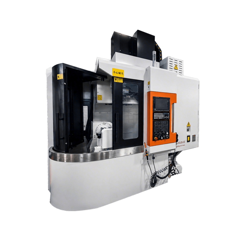
At our group, we approach every High Precision Machined Parts project with a material-specific machining strategy. Techuse Machinery operates a diverse fleet of CNC equipment: high-speed 5-axis machining centers (up to 30,000 RPM) for aluminum components like liquid cooling plates and AI server modules, and high-torque, heavy-duty milling machines (up to 300 Nm) for stainless steel and titanium parts used in aerospace and medical applications.
Our tooling division, SEMICH Precision Technology, supports these operations by recommending the correct tool holder (HSK or SK) and cutting tool geometries for each material, as well as providing real-time process parameter guidance. This integration ensures that every Equipment & Tools For High Precision Machined Parts we deploy is optimized for the specific material being machined.
Frequently Asked Questions (FAQ)
- Q1: How does Suzhou Kokosili International Trading Co., Ltd. select the right spindle specification when a project involves multiple materials (e.g., a component with aluminum housing and stainless steel inserts)?
A: We base our selection on the most demanding material in the family—in this case, stainless steel. We ensure the spindle can deliver the required torque for stainless steel operations, then we program the aluminum operations to run within the available speed range. If the spindle is high-speed optimized (e.g., 25,000 RPM but only 70 Nm), we may consider manufacturing aluminum and stainless steel components on separate machines to maintain optimum productivity for each. Our engineering team performs a comprehensive power-torque-speed analysis during the quoting phase, using our in-house databases of material-specific cutting coefficients, to identify the best machine allocation. - Q2: What specific toolholding and balancing standards does Suzhou Kokosili International Trading Co., Ltd. use when machining High Precision Machined Parts in titanium at low RPM and high torque?
A: For titanium machining, we use HSK-T (toolholder version) or SK (steep taper) holders with high clamping force. All tool assemblies are balanced to G2.5 at the maximum operating speed, but more importantly, we ensure that the holder interface can withstand the high torque without slipping. We apply torque-controlled tightening (using a torque wrench) to standardize clamping force. Additionally, we use hydraulic or shrink-fit chucks for better runout control (TIR < 0.005mm), because tool runout becomes critical when cutting titanium at low speeds—it increases localized heat generation and accelerates tool failure. SEMICH Precision Technology provides guidance on holder selection and maintenance intervals specific to each material group. - Q3: How does Suzhou Kokosili International Trading Co., Ltd. ensure that the programmed spindle speed and feed rate will result in stable cutting without chatter when machining High Precision Machined Parts of difficult materials?
A: We combine a three-step verification process. First, our CAM software incorporates material-specific cutting force models and stability lobe diagrams to predict chatter-free spindle speed zones. Second, we perform a dry-run (air cut) and use spindle power monitoring to verify that the machine is not approaching its torque limit. Third, we conduct a test cut on a sample workpiece and analyze the sound, chip formation, and surface finish. If needed, we adjust the speed by ±10% to find the stable lobe center. For very critical aerospace components, we also use an accelerometer on the spindle to detect vibration harmonics and fine-tune the RPM. All of these process parameters are documented and stored in our tooling database for future repeat orders, ensuring consistent quality across production runs.
