

 English
  русский
  عربى
عربى 






Probing Strategy: Why the Same CMM Gives Different Numbers on the Same Part
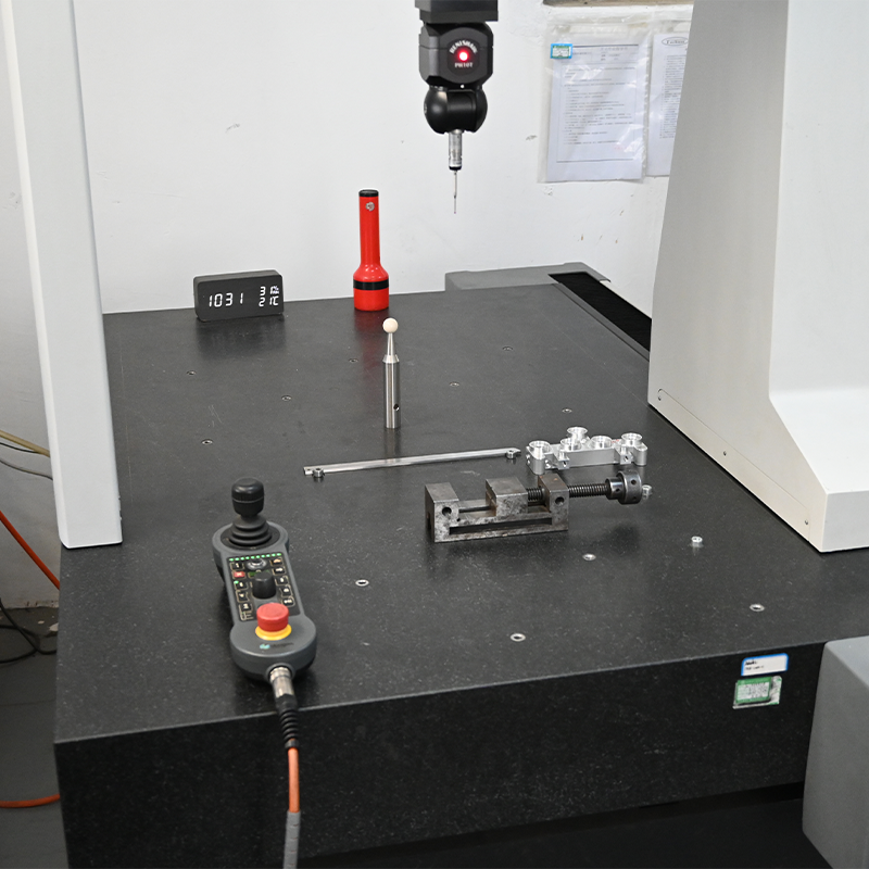
A coordinate measuring machine is only as accurate as the strategy behind each probe touch, the machine itself is rarely the limiting factor. Probe approach angle, stylus deflection compensation, and the number of points sampled per feature all influence the reported dimension, sometimes by more than the tolerance band the part is being checked against. A circular bore measured with four points spaced 90 degrees apart will report a different diameter than the same bore measured with twelve points, because four points can't detect lobing or out-of-roundness that a denser sample catches immediately. This is why Suzhou Kokosili standardizes point density and probe path by feature type rather than leaving sampling strategy to operator discretion during first-article inspection.
Stylus tip diameter matters just as much. A 2mm ruby tip probing a small internal fillet reports a different effective surface than a 1mm tip would, since the tip's own geometry gets subtracted mathematically from the raw touch point, and using the wrong tip size for a feature's radius introduces a systematic offset that no amount of repeat measurement will correct.
Reading GD&T Correctly: Where Most Inspection Reports Go Wrong
Geometric dimensioning and tolerancing callouts describe a datum reference frame, not just a shape, and measuring a feature without first establishing that frame correctly is one of the most common sources of disputed inspection results between a supplier and a buyer. A true position callout referenced to datums A, B, and C means nothing if the CMM software constructs the coordinate system in a different order or with a different datum priority than the drawing specifies. Our quality team, operating out of the same facility where the parts are machined and cast here at Kokosili, builds the datum reference frame in software before touching a single measurement point, so the report matches the drawing's intent rather than a convenient approximation of it.
Primary, secondary, and tertiary datums must be constrained in the sequence the drawing specifies, not reversed for convenience.
Flatness and straightness are evaluated independently of location, mixing the two produces a misleading pass or fail.
Bonus tolerance at maximum or least material condition is often left unclaimed, tightening acceptance criteria unnecessarily.
Complex surface profiles require dense point clouds compared against nominal CAD, not a handful of discrete checks.
Measurement Uncertainty and Traceability: The Number Behind the Number
Every CMM measurement carries an uncertainty budget, and reporting a dimension without acknowledging it gives a false sense of precision. Temperature is the largest contributor in most shop environments: a 300mm aluminum part measured at 25°C versus 20°C shifts dimensionally by roughly 0.033mm from thermal expansion alone, which can consume a meaningful fraction of a tight tolerance band before the probe even touches the part. Traceable calibration back to a national or ISO reference standard closes that gap, but only if calibration intervals are actually enforced rather than treated as a paperwork formality.
- Calibrate reference artifacts on a fixed schedule traceable to a recognized national standard.
- Log ambient temperature and humidity at the time of measurement for temperature-sensitive tolerances.
- Cross-check CMM results against optical projection or gauge data periodically to catch systematic drift.
- Retain raw point-cloud data, not just pass/fail summaries, for parts subject to audit or dispute.
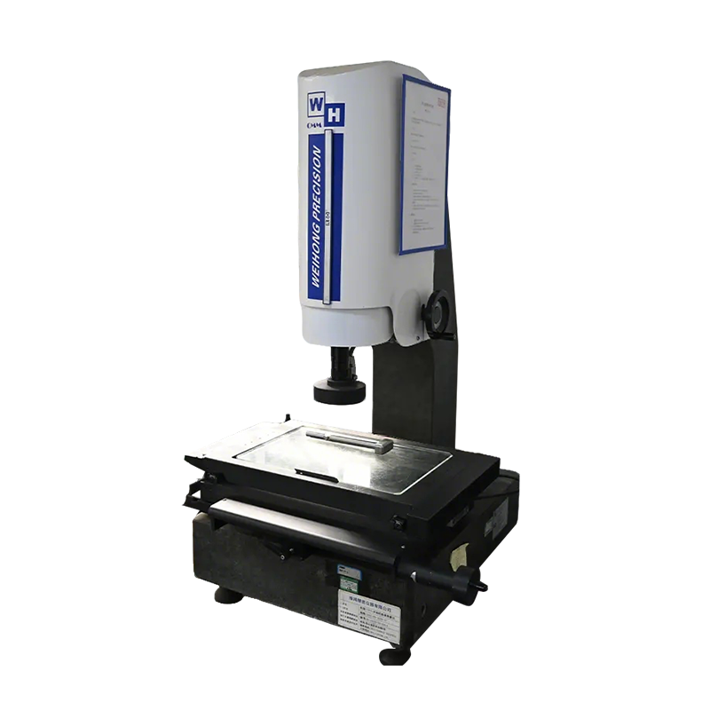
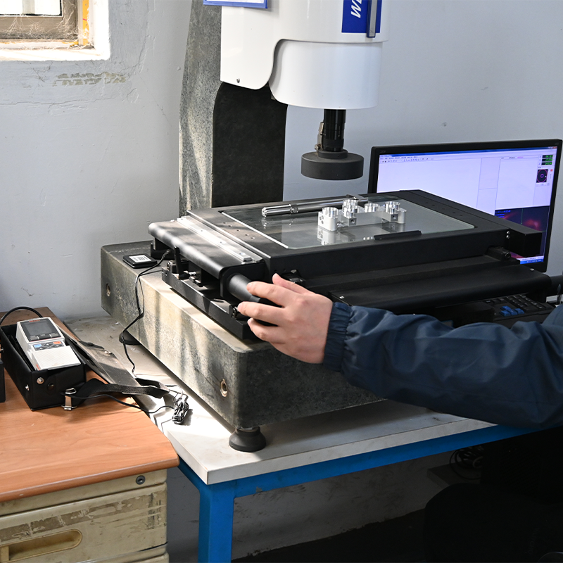
Optical projection inspection complements this by verifying 2D contours and hole spacing quickly through non-contact imaging, catching the kind of first-article deviation that a slower point-by-point CMM cycle might not flag until much later in a production run.
Matching Inspection Depth to Industry-Specific Risk
Not every part warrants the same inspection depth, and applying a blanket standard across all programs wastes cycle time on low-risk parts while under-inspecting the ones that actually carry consequence. Aerospace brackets typically require full dimensional reports with traceable calibration records on every unit, because a single undetected deviation can compromise structural certification. Energy storage housings prioritize flatness and sealing surface accuracy, since a warped enclosure compromises thermal contact long before it fails any single dimensional check. Automotive components split the difference, leaning on statistical process control sampling for high-volume runs rather than full CMM inspection on every part.
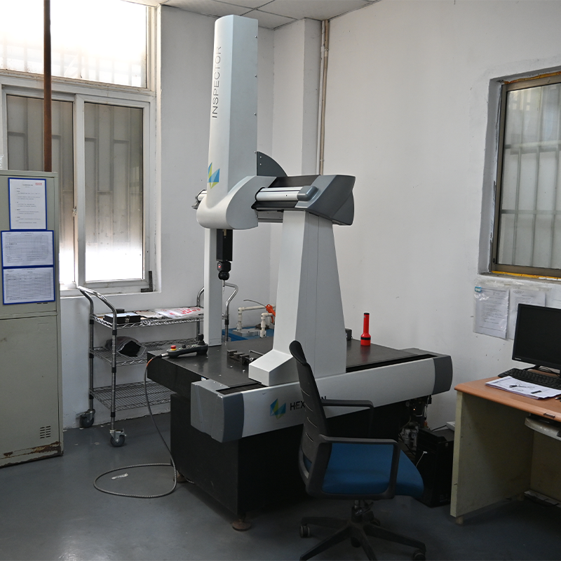
What determines whether an inspection plan actually catches problems, rather than just generating paperwork, is whether the measurement strategy was designed around the part's specific failure risk in the first place. Buyers sourcing suppliers with High-precision Coordinate Measuring Machines (CMM) on the shop floor should ask how sampling frequency and datum strategy are decided per part family, not just what equipment sits in the inspection room, since the equipment on its own guarantees measurement capability but not a sound measurement plan, a distinction reflected in how inspection programs are set up around High-precision Coordinate Measuring Machines (CMM) at Kokosili.
