

 English
  русский
  عربى
عربى 




Liquid Cooling Loop Design: Matching Pipe Diameter, Pump Head, and Radiator Area Based on TDP and Flow Rate Requirements
In thermal management systems for AI servers, data centers, and energy storage modules, the Liquid Cooling Loop is the critical pathway that removes heat from high-density power components. Designing an efficient loop requires careful coordination among three core variables: pipe inner diameter, pump head (pressure), and radiator heat exchange area. These parameters cannot be optimized in isolation—they are interdependent and must be matched to the system's thermal design power (TDP) and target flow rate. This article provides a systematic methodology for achieving this balance, based on principles of fluid dynamics and heat transfer.
Fundamental Relationships in Liquid Cooling Loop Design
The performance of any Liquid Cooling Loop is governed by three interconnected physical laws:
- Energy balance (heat transfer): Q = ṁ · Cp · ΔT, where Q is heat load (TDP), ṁ is mass flow rate, Cp is coolant specific heat, and ΔT is the temperature rise across the cold plate.
- Pressure drop (hydraulic): ΔP = f · (L/D) · (ρv²/2), where pressure loss depends on pipe length (L), inner diameter (D), fluid velocity (v), and friction factor (f).
- Heat exchanger performance: Q = U · A · LMTD, where A is radiator surface area, U is overall heat transfer coefficient, and LMTD is log-mean temperature difference.
Step-by-Step Matching Process for Liquid Cooling Loop Components
1. Determining Pipe Inner Diameter Based on Flow Rate and Velocity
Pipe diameter selection is the foundation of loop design. For a given target flow rate, the inner diameter determines fluid velocity, which directly affects pressure drop and heat transfer coefficient.
- Target velocity range: For water-based coolants, recommended velocities are 1.0–2.5 m/s. Below 1.0 m/s, heat transfer is inefficient; above 2.5 m/s, pressure drop escalates rapidly and erosion-corrosion risks increase.
- Diameter selection formula: D = √(4Q_vol / (π · v)), where Q_vol is volumetric flow rate and v is target velocity.
- Practical guidance: For TDP up to 300W (server CPU), 8–10mm ID is typical; for 1–3kW (rack-level distribution), 12–16mm ID; for 5–20kW (data center CDU), 25–40mm ID.
2. Pump Head (Pressure) Requirement Estimation
Once pipe diameter and flow rate are fixed, the required pump head is determined by summing all pressure losses in the loop—including straight pipes, fittings, bends, cold plates, and the radiator.
- Straight pipe loss: Proportional to length and inversely proportional to diameter⁵. Longer or narrower pipes significantly increase head requirements.
- Local losses (fittings, valves, blocks): Often represented as equivalent lengths. A typical CPU cold plate may add 0.5–2m of head loss; a radiator can add 1–3m.
- Total head requirement: Sum of all losses + a safety margin (typically 15–20%) to account for filter clogging and aging. Total head is expressed in meters of water column (mWC) or pressure (bar).
- Pump selection rule: Choose a pump whose maximum head exceeds total system loss at the design flow rate. Operating point should be near the pump's best efficiency point (BEP).
3. Radiator (Heat Exchanger) Sizing
The radiator must dissipate the full TDP while maintaining the coolant inlet temperature within acceptable limits (typically ≤ 45°C for AI server cooling).
- Required heat transfer area: A = Q / (U · LMTD). For air-cooled radiators, U ranges from 20–60 W/m²·K depending on fin density and air flow (fan speed).
- Air-side constraints: Radiator area must be matched with fan capacity. Typical air flow requirement is 5–10 CFM per 100W of heat for effective heat rejection.
- Coolant-to-air temperature difference: A minimum 10–15°C delta is needed for economical radiator sizing. Smaller deltas require exponentially larger radiators.
Quantitative Comparison: Sizing Examples for Different TDP Levels
The following table provides reference design parameters for Liquid Cooling Loops at three common power levels:
| TDP (Heat Load) | Recommended Flow Rate (L/min) | Pipe Inner Diameter (mm) | Estimated Pressure Drop (mWC) | Required Pump Head (mWC) | Radiator Area (mm²) at 2,000 RPM Fan |
|---|---|---|---|---|---|
| 300W (single server CPU) | 3–5 | 8–10 | 3–5 | 6–8 | 150 x 120 (180 cm²) |
| 1.5kW (rack manifold distribution) | 10–15 | 14–16 | 5–8 | 10–15 | 250 x 250 (625 cm²) |
| 8kW (data center CDU loop) | 30–40 | 25–32 | 8–12 | 18–25 | 500 x 400 (2,000 cm²) |
Practical Design Pitfalls to Avoid
- Oversizing pipe diameter: Reduces velocity, which lowers the heat transfer coefficient and may cause sedimentation or air pocket accumulation.
- Undersizing pump head: Results in insufficient flow at operating conditions, causing higher component temperatures and potential thermal throttling.
- Radiator area insufficient: Forces coolant to return at elevated temperatures, reducing the thermal margin for downstream components.
- Ignoring elevation changes: Vertical lifts of 1–2m can add significant static head that must be included in pump selection.
Our Integrated Capabilities in Liquid Cooling Loop Production
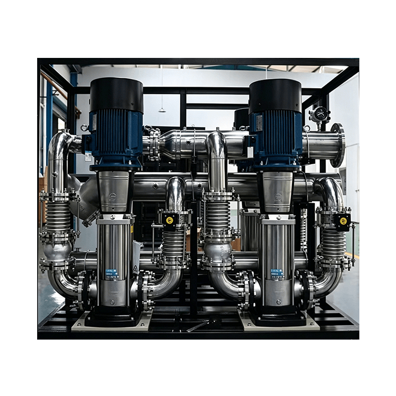
Our group, through Techuse Machinery, specializes in the precision manufacturing of Liquid Cooling Loop components including cold plates, water distributors, flow manifolds, and precision pipelines. Our 9,000m² CNC plant enables us to produce complex geometries with tight tolerances for sealing and flow distribution, while our 10,000m² precision casting facility supplies near-net-shape manifolds and pump housings for high-volume programs.
SEMICH Precision Technology provides the cutting tools and technical support required for machining critical surfaces and threads on Liquid Cooling Loop components, ensuring that pressure-bearing joints maintain leak-tight integrity. Cocosili handles global logistics and customer communication, delivering complete cooling solutions for new energy, data center, and aerospace applications.
Frequently Asked Questions (FAQ)
- Q1: How does Suzhou Kokosili International Trading Co., Ltd. validate that the designed Liquid Cooling Loop will meet the required TDP before committing to production?
A: We utilize a three-step validation process. First, our engineering team performs 1D thermal-hydraulic simulation (using tools like Flowmaster or Amesim) to predict pressure drop and temperature distribution across the entire loop. Second, we build a prototype and test it on our in-house thermal test bench, which can simulate up to 20kW of heat load with real-time data acquisition. Third, we conduct a design of experiments (DOE) to verify the sensitivity of performance to manufacturing tolerances. This systematic approach ensures that every Liquid Cooling Loop we produce meets its thermal specifications under actual operating conditions. - Q2: What manufacturing capabilities does Suzhou Kokosili International Trading Co., Ltd. offer specifically for Liquid Cooling Loop pipe assemblies and manifolds that require complex internal flow paths?
A: We offer both CNC machining and precision casting for Liquid Cooling Loop components. For complex manifolds with internal cross-drilled passages or curved channels, we use 5-axis CNC machining from solid aluminum or copper blocks to achieve leak-proof, high-pressure designs. For higher volumes, our casting facility produces near-net-shape manifolds with reduced material waste. All components are subjected to helium leak testing (to 1×10⁻⁶ mbar·L/s) and pressure cycling tests (1.5x working pressure) to guarantee reliability. We also provide custom pipe bending and welding services for complex routing requirements. - Q3: How does Suzhou Kokosili International Trading Co., Ltd. ensure the compatibility of materials within a Liquid Cooling Loop to prevent galvanic corrosion over long-term operation?
A: We address this through a combination of material selection and surface treatment. We recommend using closed-loop materials with similar galvanic potentials—primarily copper and copper alloys or aluminum with appropriate corrosion inhibitors. For mixed-metal systems (e.g., copper cold plates with aluminum radiators), we apply specific coatings such as nickel plating on copper or anodizing on aluminum to create passive barriers. We also work with our coolant supplier partners to recommend corrosion-inhibiting additives (like triazole-based inhibitors) that are compatible with the entire loop. Our manufacturing process ensures that all joints are sealed to prevent fluid migration, and we perform salt spray and thermal cycling tests to validate long-term compatibility before releasing products to production.
